Raising the Bar -A Barcode Scanner
An undergraduate team project in microprocessor applications.
Executive Summary
In our daily lives we often encounter barcode scanners, usually, in the check-out lines in supermarkets and in retail stores, this project is a basic barcode scanner which uses a regular white 8 ½ by 11-inch sheet of paper for the barcode and a generic infrared transmitter and receiver for scanning. The infrared transmitter used for this project is not by any means spectacular or powerful and it may be found in a college student’s lab kit. When D.C. current is supplied to the transmitter, it emits a narrow beam of infrared light, which is invisible to the human eye. The infrared receiver used in this project, just as the transmitter, is simple as well. When this receiver, which acts as a variable resistor, detects infrared light, its resistance increases. This results in an increase in the percentage of the 5V that it takes up. That means an increase in the voltage difference. This is noticeable when combined with a large enough resistor.
When the barcode is scanned for its binary code, the transmitter shines an infrared light beam onto the surface of the barcode; the white surface reflects the infrared beam off of itself, while the black surface absorbs a substantial amount of the infrared beam. Thus, the infrared receiver, which is effectively angled for best results, will detect the reflected light from the white surfaces, but it will not detect a significant amount of reflected light from the black surfaces. The reading of the barcode is simply a reading of the voltage drops that happen or do not happen to the infrared receiver as a result of it receiving or not receiving reflected light. The barcodes used in this project are divided into eight sections, where each section corresponds to a “bit” of an eight-bit binary number. When the receiver does not detect infrared light during one of its eight scanning phases, it is recorded as logical ‘1’ and detected infrared light is recorded as logical ‘0’.
The heart of the entire system is the Motorola HC11 microprocessor. It coordinates the following: storage of received data, processing of received data, the operation of the print feeder, and screen output. All of the programming in assembly language makes the hardware setup much simpler than it really should be. Bringing all of this together is the HC11 as it tells one their fortune by the barcode that describes them. Where will you live in the future?
The Design Process
Transmitter/Receiver
This design project requires the use of a transmitter and a receiver as a sensor because it must detect a barcode (white and black bars). Black is logical ‘1’ and white is logical ‘0’. The transmitter and receiver are angled toward each other:

When the transmitter and receiver are over the black bar the printing will absorb the infrared light so the receiver will not receive it. When the transmitter is over the white bar it will reflect the signal and the receiver will receive it. This part of the design process consisted of building the transmitter and receiver circuit and connecting the output (the resistance across R1 and R2) to a comparator (the LM311) in order to get a 0 or 5-volt output (see fig.1 in appendix) as an input to the HC11.
The transmitter is connected to R3=1k resistor to 5 volts. The receiver is connected to R1 and R2 in series (1640k resistance in total, two 820K resistors) to ground to get a recognizable voltage drop (about 1.3 volts). The output from the transmitter and receiver is connected to pin 2 (the input) of the comparator LM311, pin 3 that is input also, is connected to +3 volts. The comparator compares the output voltage from the receiver with 3 volts. When the output from the receiver is over 3 volts (the transmitter and receiver are detecting the black bar) the comparator will output +5 volts or a logical ‘1’ to Port C0.
HC11 Microcontroller
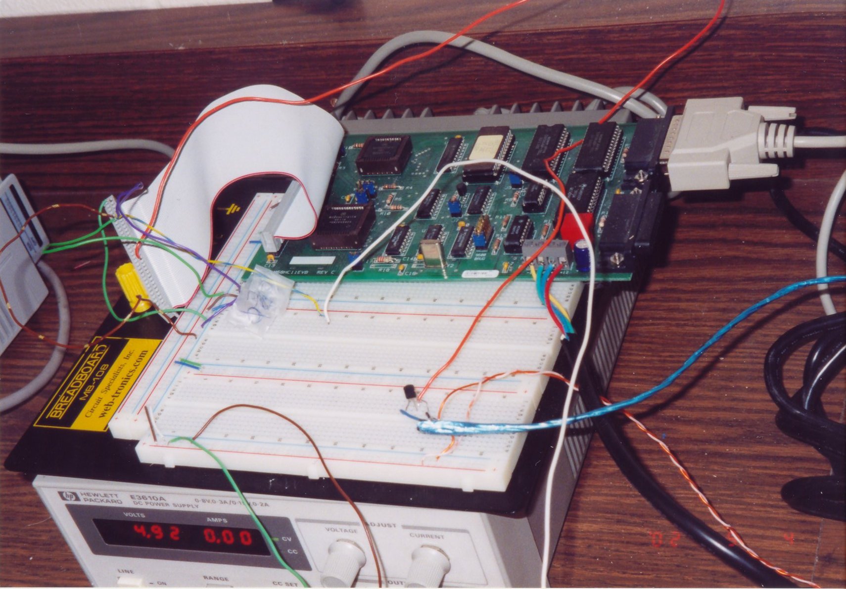
The HC11 Microcontroller was used as an abstract “box” in our design project. The “box”, or brains of the design project, contained connections to inputs and outputs. The microcontroller interfaced between the printer feeder mechanism and the BUFFALO monitor program and displayed it on a PC monitor. The microcontroller input was from channel PC0 on PORTC. The Data Direction Register was set ($F0) to allow inputs on only the lower nibble of PORTC. We grounded PC1, PC2, & PC3 to allow only PC0 because the design project required only 1 input channel. The input PC0 came from the comparator as +5 V or +0 V depending on whether a dark or light region was detected. The outputs from the microcontroller were both used by the printer feeder and the BUFFALO monitor. A +5 V output from the microcontroller PB7 signaled the printer feeder switch to begin, while 0V, signaled the printer feeder to terminate. Parallel output from the microcontroller was displayed on the screen by the BUFFALO monitor program. The entire microcontroller was powered by a standard 120 V AC source stepped down to +5 V DC. The microcontroller was reset easily by pressing the red reset button and then loaded using TeraTerm.
Printer Feeder
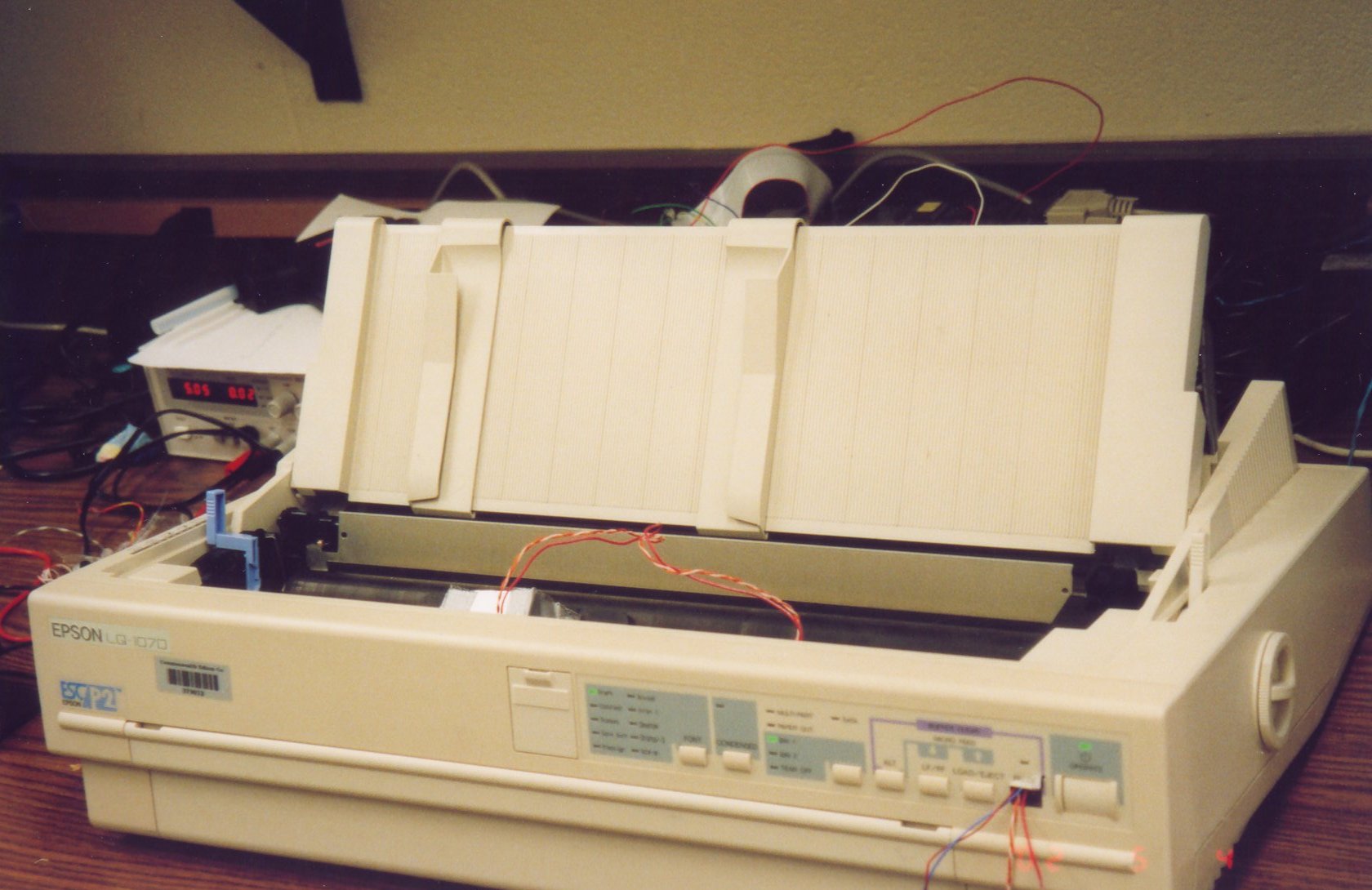
We set out to use part of a printer as a paper tray with paper rollers. We would have added a D.C. motor to power the paper feeder. When the used printer had all its the motors and gears intact it was decided that the stepper motor that was contained within the printer would be used to feed the paper. We ran into unforeseen problems (detailed in Problems Encountered) and had to scrap the entire printer. Another printer was used instead and it was impossible to find any literature on how to set up the EM 155 stepper motor that was in the Epson LQ 1070 printer.
Therefore we examined other quick ways to set up a printer to move paper through itself by control of an HC-11. We looked at the form feed (LF/FF) button as a possibility but it seemed a little choppy in the feeding of the paper because it started moving in an odd pattern. We decided to use the LOAD/EJECT button because once the button is pressed the paper was fed smoothly out of the printer at a constant speed. We opened up the printer and found out how to trigger the printer’s EJECT by connecting S3 contact #1 to an S3 contact #2. This served as a way to trigger the LOAD/EJECT button without having to press the button. Using a 2N3904 transistor and long wires we could connect an output from PORTB to the B pin of the transistor. This would control the connection of the 2 other contacts when a 5V pulse was output to the transistor. This became an efficient switch. It goes like this:
- The paper is loaded into the printer by the user.
- The printer automatically feeds the printer until the very beginning of the paper is lined up with the transmitter/receiver.
- The HC-11 waits for computer input of ‘Y’ to start the reading of the barcode.
- The ‘Y’ is pressed and the printer is EJECTing the paper at a constant speed of 4.8 seconds for an entire 8.5″x11″ sheet of paper.
- The paper is finished and the printer stops attempting to EJECT the paper and it is finished, waiting for another barcode to be read.
Software Design
The conceptual part of the software design involved three main components: the initial startup, the process of scanning in data, and translation of input to output.
The initial startup subroutine involved 1.) Clearing TOTAL, the variable that the input data would be stored on, and 2.) Setting the data direction registers of PORTC to allow input. Also, a welcome message was printed on the screen to allow user input from the keyboard. The keyboard ASCII input character was then converted to a capitalized character and then compared to the ASCII code for the character ‘Y’. Thus, if the keyboard input were either ‘Y’ or a ‘y’, then the input would be converted to a ‘Y’ and compared to the ASCII code for a ‘Y’. If the codes match, then the READ subroutine would initiate. Otherwise, the welcome menu and user input prompt would be repeated.
The READ subroutine sampled readings from PORTC channel 0, PC0, and stored them in TOTAL. There were timed delays implemented for each sampling. The total time (4.8 seconds) for the paper to feed through the printer was determined and used to calculate the time delay for sampling for each bit. Each bar required a time of 4.8s/(8*2) for the sampling process. The time for each bar was divided by two to ensure the accuracy and reliability of the sampling process. The sampled bit (either a ‘1’ or a ‘0’) was then stored in TOTAL. The process of scanning subsequent bits after the initial bit involved left shifting of the bits stored in memory located in TOTAL to allow storage of new sampled barcodes. The end result was that the first barcode data input was stored as the most significant bit of TOTAL and the last barcode data input was stored as the least significant bit.
The last component of the software design is the processing of the input data stored in TOTAL to an output on the screen. Two bits each, starting from the LSB, are considered for each word. After these two bits are considered, the next bits are considered after shifting to the right twice and the next two bits after shifting them four times and the two MSB after shifting them six times. (See figure 5)
This process will allow us to read each two bits at a time without having to list too many chunks. The two LSBs will be for the noun and this lookup table will have the word cardboard box, cabin, jail or mansion. The next two bits are for professor names: Prof Tougaw, Gelopulous, Treanor, and Cher. The number of years will be in the next two bits, which are 73, 6A, 0110, and XIV. Finally, the two MSBs will be for moods, which are suicidal, ecstatic, loco and destitute. The program will look up each category and will print out the output to the screen. These categories will be to fill the blanks between assigned sentences (SENT1-SENT4).
Barcode Input
The barcodes used for this project are white sheets of 8 ½ by 11-inch paper. Each sheet contains eight separate long rectangular sections that are either black or white. The system’s infrared receiver will read each blackened area as a logical ‘1’ and each white area as a logical ‘0’. Since there are eight sections containing either a ‘1’ or ‘0’, an eight-digit binary number is given for each barcode sheet.
To add flavor the demonstration of our project a Madlib has been incorporated. A Madlib is a play with sentences in which words are periodically removed from the sentences and replaced with a blank space. The blank space is then filled in with a corresponding word. The sentences do not have to make complete sense and the purpose of the Madlib is to have fun. An example of one our Madlibs is: “Miss Cleo says, ‘In the future, you will live in a cabin with Professor Tougaw for 73 years and be loco.'” The underlined words represent the blank spaces that were filled in with corresponding words. Each barcode sheet of paper not only contains the number that the receiver read but also a corresponding Madlib.
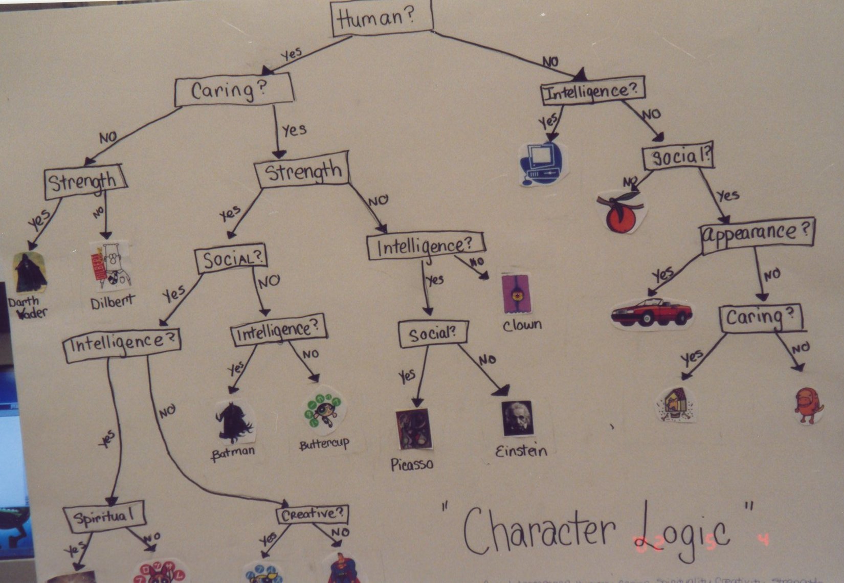
To farther add more flavor to this project a Character Personality Matching Test has been incorporated. In this game, a person will answer eight questions about himself by choosing between one of two answers. His answers are then matched with a particular person, animal or object and the same will be written to the screen. He will answer these questions by darkening a blank barcode sheet.
Screen Output
The screen output begins with the following introduction:
UPC Reader Version 1.1
Instructions:
1.) Load paper into printer feeder.
2.) Press Y when ready to scan.
After a sheet of barcode paper is loaded into the printer and the HC11 controller is initiated, the screen displays the results of the barcode scan. Depending upon which process of operation is chosen, either Mablib or the Character Personality Matching Test processes, the screen will display the eight-digit binary number with its corresponding Mablib statement or it will display a character’s name.
Problems Encountered
We came up against many problems when we thought we had smooth coasting the rest of the way. A barcode was printed in addition to setting up a primitive transmitter/receiver in an attempt to find out how large of a voltage drop we could get out of a barcode and weak transmitter/receivers. We couldn’t figure out how to get more than 200mV from the setup. We decided to use a very large resistance to get a larger drop and we got the drop to about 1.5V (easily recognizable by an LM 311).
We got an old printer donated by EIS at Valparaiso University and we began to work on it. We found some specifications for the stepper motor NMB PM55L. We couldn’t get it to work and we tinkered with it for about 5 days (while the code was completed). We wasted time and we finally got it to work with help from 2 professors (thanks). We tried to reattach the motor but we had lost a gear and the stepper motor was useless to us without being attached to the printer. We decided to find another printer.
We got one donated by Jon Sanders and we couldn’t find the specifications for the stepper motor in the Epson LQ 1070. We got the paper to feed by using a transistor, instead. We decided this because we were running out of time. It worked nicely though.
The last major problem was when we were getting inconsistent outputs from the comparator. We had the entire circuit on a tiny board (placed where the print head normally goes). The circuit board was just a cut up board from elsewhere and we were trying to use the outside pinholes. They didn’t work consistently unless the wires were pressed against the board. This took very long to debug because it would work a lot of the time. We finally had to redo the entire wiring so that none of the wires used the outside pinholes. After this, it has worked incredibly consistently.
Conclusions
We found out in an untimely fashion that we should have spent less time on the hardware design and more time on the software design. There are so many different things that we could have programmed using menus for the barcode scanning. If we had more time then we would have been able to show our abilities learned from ECE 320 a lot better than we actually did. We had some challenging programming, but most of our time was spent trying to get a stepper motor to work correctly. The embellishments that could have been added would have included many possibilities that have to do with any sort of data collection. We could have done something to program in an answer key read-in and the value input as graded against the answer key. It was interesting to find out that all of the work on trying to get a stepper motor working properly could have been avoided by using a days work and a transistor to get a printer to do what it already does well (feed paper through at a constant speed). If we had started out with the printer that we did end up with then we could have used some more of its features and we could have put the LED’s to work for us. Another thing that we learned, is that plenty of organization and good wiring will pay off in the long run and the opposite will only come back to haunt you. Last, and most importantly, we learned how to scrounge around and find old printers to put to good use and how to use cheap parts from GE 100 (transmitter/receiver).
Appendix
- Figure 1 – Schematic
- Figure 2 – Waveforms of Output of Transmitter/Receiver
- Figure 3 – Acceptable level of Transmitter/Reciever
- Figure 4 – Flowchart of basic operations of barcode reader
- Figure 5 – Input Process Algorithm
- Assembly Code for Madlib Program
- Assembly Code for Character Match
The Engineering Design Expo
Every year the College of Engineering at Valparaiso University holds a design expo where students display their projects and offer demonstrations of their projects. Here are a few photos of my project displayed in the expo and of the actual hardware implementation.
- Poster
- Poster and Surveys
- Microcontroller and Circuitry
- Character Logic Poster
- Automatic Printer Feeder
Presentations
My Solution Code
You can view and download the GitHub repository here.